Published: Jul 29, 2019 by Richard Musil
VR headset rendered FOV calculation
Basic theory
The idea about using angular dimensions to describe the field of view has been there probably since the beginning of the 3D rendering, e.g. OpenGL. It was then popularized by the first person shooters (read Quake), because there, users could actually appreciate its significance.
Setting a large “FOV” in Quake, could get you a competitive advantage (and a sick image), because you saw more than those who did not do it. What you actually set there back then was the visible horizontal angular range. Clearly it would not be a sufficient parameter to describe the natural field of view of the human eye, as this is much more complex, depending on the face anatomy, the optical acuity, etc. Luckily the 3D rendering technology works with much simpler geometry - in fact it can only render into rectangular frames.
Knowing the angular dimension in one direction and knowing the aspect ratio of the rectangle gives automatically the other angular dimension. The horizontal was probably chosen, because it seemed more important in daily life and so the “FOV” in the computer (game) graphics was defined.
3D rendering pipeline uses perspective projection which relies on mathematical transformation of the objects from the 3D space into the 2D computer display. This transformation is defined by the viewing frustum.
The image below is a visualization of the angular dimensions in a mono view (single eye) projection. The blue rectangle shows the shape (the aspect ratio of the horizontal vs vertical dimension) of the viewing frustum’s projection plane, the intersecting colored triangles show the individual angular ranges, the line perpendicular to the rectangle where all three triangles intersect, is the view axis, and the eye is at the tip. View axis is always perpendicular to the projection plane, or here to the “shape” plane.

The magenta triangle marks the horizontal FOV (the horizontal angular range), the yellow triangle marks the vertical FOV (the vertical angular range) and the cyan triangle marks the diagonal FOV. The exact values with which this image was rendered were: 120.0° horizontal, 88.5° vertical and 126.6° diagonal. The horizontal value and the aspect ratio (16:9) were chosen, the rest was calculated. The red “clown noses” mark the terminal points of the angular ranges (FOVs) in their respective directions. Let’s call them FOV points as they will have some significance later.
Immutable property of the rendered image
What is important to understand is that the image rendered at a particular FOV does not necessarily need to be observed at this FOV. Imagine that the blue plane in the picture was a TV, and the image on the screen was showing a scene with 120° horizontal FOV. Then to perceive the image naturally (i.e. with the objects in the correct places) one would have to have the eye exactly at the pinnacle of all three triangles. Which means quite close.
But if you move further from the screen, you will still see the same picture, with “120 degree content”, but the angle at which you will observe it will be much smaller (for example only 30 degrees), so the perspective will not match - you will lose the angular verity. The objects will look deformed, especially close to the edge of the screen.
To put it differently, if you want to observe the scene correctly with the respect to the 3D properties of the objects in the scene, i.e. their sizes and positions, you need to have also the viewing angles correct. This is only possible from the precise spot, defined by the view geometry used for the rendering.
The another consequence, probably even more important for the following explanation, is that once the scene is rendered, it encompasses the exact amount of angular range it was rendered for. Even if you choose to display it on a larger or curved screen, or look at it from the closer distance, you would not see more information (more FOV) than there was from the beginning. Everything which was originally in the virtual 3D space inside the viewing frustum pyramid is in the image, everything which was outside is not.
The viewing frustum and the way how the perspective projection works also ensures that the visibility (i.e. whether the object is rendered into the image or not) does not depend on the distance from the eye, only on the angle at which the object is observed from the viewing axis. (For practical reasons though, the engines do not render the objects beyond certain distance = far clipping plane, nor closer than another distance = near clipping plane.)
Stereo view
Having the theory for the mono view in place, we can move to the stereo view. This is also not new. The stereo rendering has been there for ages, but only with VR it really went into the mainstream.
In stereo rendering the scene is rendered from two different spots (eye positions) and then somehow presented to the viewer. The rendering was not the problem, but until now, the presentation was. Today, with a VR headset, we have finally the technology to do it.
The following pictures shows the view geometry of the original HTC Vive (OG Vive) headset. One point needs to be clarified first. The blue planes are not the headset displays, because if they were, they would have to be too close to the eyes. They are simply just “shape planes” (clipping the view), helping to visualize the shape (cut) of the viewing frustum used for the scene rendering at a particular distance from the eye.
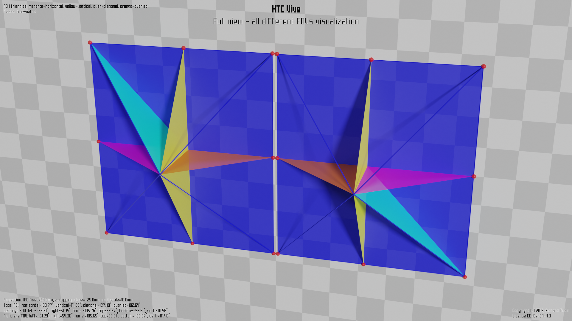
The thing is, with a VR headset, we cannot look at the screens with the naked eye because the exact viewing spot to preserve the angular verity is too close, so the panels would have to be very small to fit around the face and also it would be quite uncomfortable (even impossible) to focus at such short distance.
Therefore we use lenses to place the panels (optically) further away and also to put their (virtual) focal distance even further, so instead, of focusing at 2 cm distance, the eye can focus at 1 m, where the virtual image is presented.
The optical tricks however are not really changing the fundamentals of how the rendering and all the FOV theory works. The scene is just rendered into two images, instead of one, while using two different viewing points and two different viewing geometries, because, the individual viewing frustums for each eye can be (and usually are) different. In the example given above the eyes are ever slightly shifted closer to the nose.
The colored triangles mark the same characteristics as already described in the mono view part above, apart from the orange one, which is new and will be described later.
The magenta is showing the total horizontal FOV of the stereo view (now composed of two parts), the yellow triangles represent the vertical FOV (here the stereo aspect does not change anything) and the cyan is the total diagonal FOV.
The new color - the orange - symbolizes the stereo overlap, introduced by the stereo view. I.e. the horizontal angular range visible by both eyes. The introduction of the stereo overlap marks another important point. The total horizontal FOV, i.e. the maximal horizontal angular range which is visible is combined value for both eyes. It means that there are some areas (at the edge of the range) which are only visible by one eye or the other (while the other one is obscured by the nose).
Putting it into a formal expression:
Total horizontal FOV = Left eye’s left view + Right eye’s right view
Stereo overlap = Left eye’s right view + Right eye’s left view
Diagonal FOV = Left eye’s top left view + Right eye’s bottom right view (or
vice versa)
Vertical FOV - remains unchanged
The exact angles are collected from the headset (driver) by OpenVR and then advertised to the application via the API.
Which means, it is the headset who defines the view geometry, which the application then uses to render the image. It also means that the geometry depends on the hardware design of the headset and its optical properties in particular.
The actual numbers from HTC Vive would look like this:
Left eye FOV:                    Right eye FOV:
    left:       -54.41 deg           left:       -51.29 deg
    right:       51.35 deg           right:       54.36 deg
    bottom:     -55.91 deg           bottom:     -55.87 deg
    top:         55.67 deg           top:         55.61 deg
    horiz.:     105.76 deg           horiz.:     105.65 deg
    vert.:      111.58 deg           vert.:      111.48 deg

              Total FOV:
                  horizontal: 108.77 deg
                  vertical:   111.48 deg
                  diagonal:   127.48 deg
                  overlap:    102.64 deg
Now, I wrote would for a reason, because in reality, they are different. Meet the HAM.
Hidden area mask (HAM)
Since the current rendering technologies only know how to render an image into a rectangle and the lenses in a VR headset mostly come in circular shapes, people realized that when used together, either some part of the lens field of view remains unused (if the full rendered rectangle fits into the lens circular FOV), or some part of the rectangular image gets obscured, if the circular FOV of the lens fits into the rectangle completely.
Because the optics is more difficult to make than the software, the decision was made to cover the full FOV of the lenses and simply mask the never seen parts of the image in the rendering. The renderer still has to do some work, but can save the effort (which is a precious commodity in VR) in the final step of the rasterization, where it can avoid the masked pixels.
The hint comes in the form of the Hidden area mask (HAM), which is a simple mesh, covering some part(s) of the original rendering rectangle. Its shape is completely dependent on the lens design and differs from one headset to another.
This is how it looks on HTC Vive:
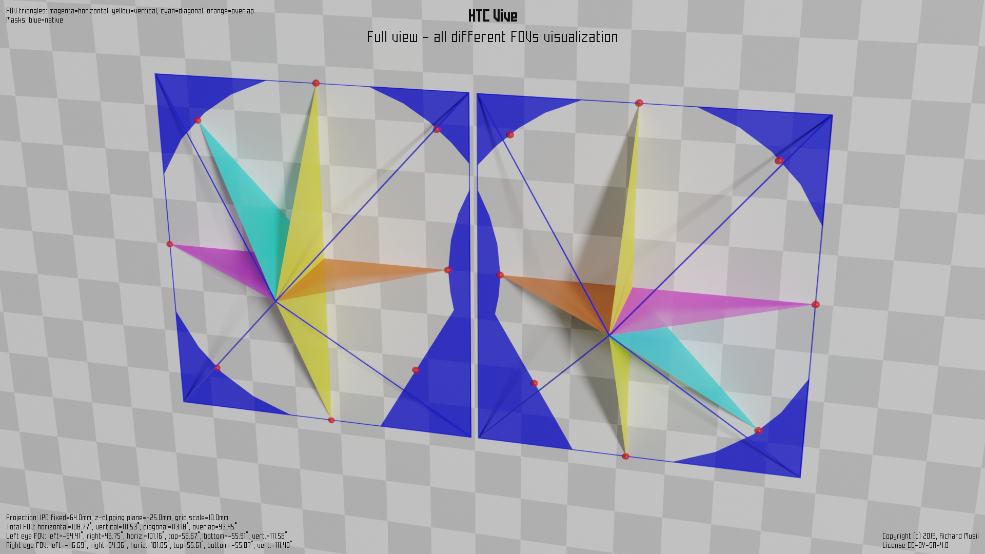
Here the blue color mesh shows the HAM and the visible part is actually the hole in it. The triangles symbolizing the individual FOVs are adapted to measure only the visible area.
And the corresponding numbers:
Left eye FOV:                    Right eye FOV:
    left:       -54.41 deg           left:       -46.69 deg
    right:       46.75 deg           right:       54.36 deg
    bottom:     -55.91 deg           bottom:     -55.87 deg
    top:         55.67 deg           top:         55.61 deg
    horiz.:     101.16 deg           horiz.:     101.05 deg
    vert.:      111.58 deg           vert.:      111.48 deg

              Total FOV:
                  horizontal: 108.77 deg
                  vertical:   111.48 deg
                  diagonal:   113.18 deg
                  overlap:     93.45 deg
What suffers most from the HAM is the diagonal FOV (obviously), but the strange shape close to the nose has also some impact on the stereo overlap. On the other hand, the vertical FOV remains the same, and the total horizontal FOV as well.
Canted screens and views
So far all the theory behind the stereo view assumed that the two views were oriented in the same direction, i.e. they were parallel to each other. Consequently the projection planes were coplanar and parallel to the face of the viewer. This concept was used in the stereo rendering for a long time.
VR changed the situation. It is more difficult to achieve a wide horizontal FOV with parallel views than, say, canted views, because the horizontal dimension of the panels (the width) increases with the arcus tangent of the horizontal angle (the magenta one in the pictures).
The idea is that by turning the displays slightly outwards, one can achieve larger horizontal coverage while saving on the panel size, and therefore also spending less effort on the rendering. It would come at the cost of a decreased stereo overlap, but this may look like an acceptable trade-off. There is nothing substantially different in rendering two non-parallel views from the previous case. At least in theory. You just set up the two viewing frustums looking “non-parallel”, but apart from that, the process itself is basically the same.
Pimax 5k+ and 8k
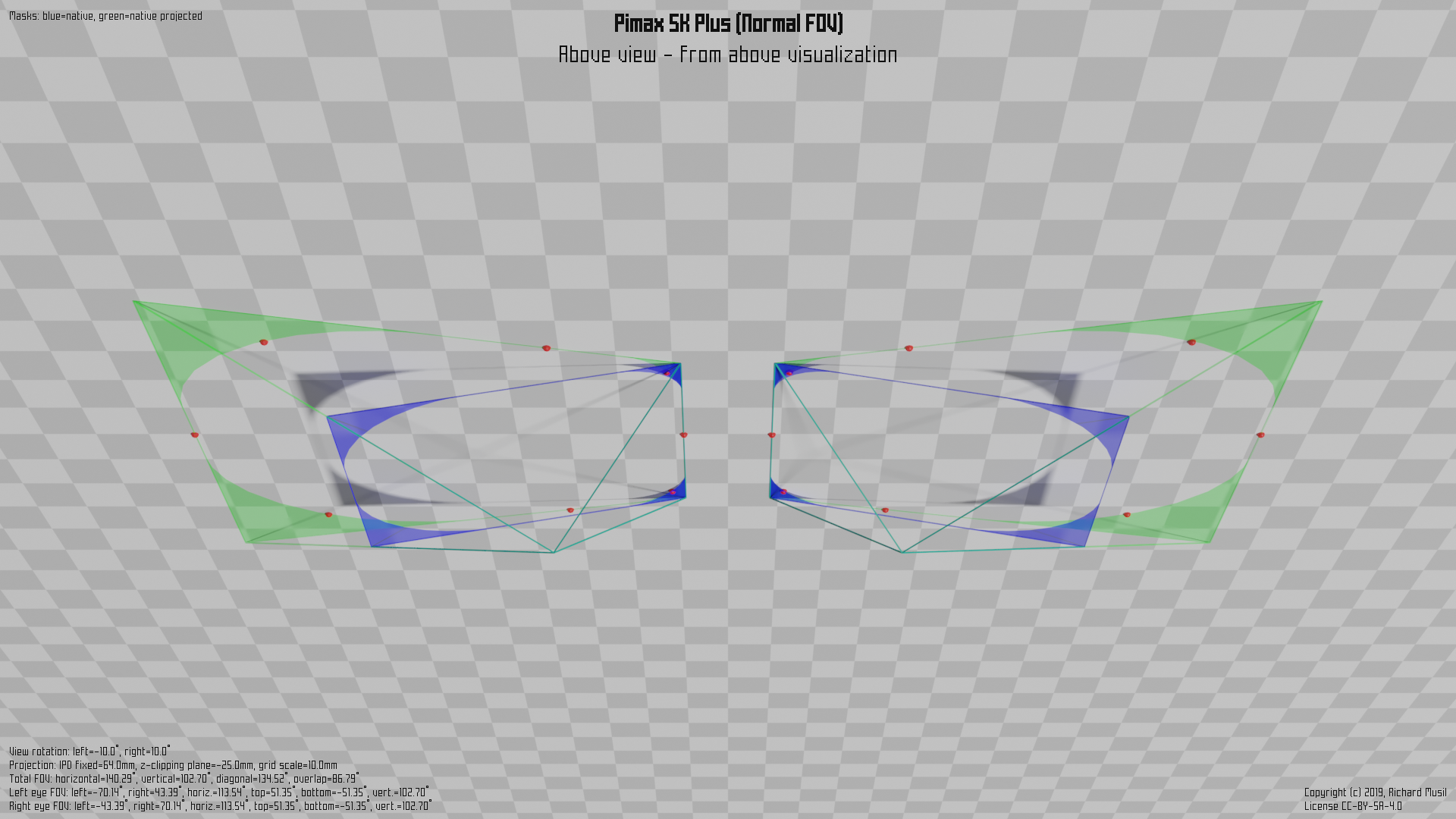
The first consumer headsets which introduced the idea in the flesh were Pimax 5k+ and 8k models. This is how the non-parallel projection is implemented on Pimax 5k+ in Normal FOV (~140° horizontally).
First the “plain” visualization without any FOV triangles to show the canting:
and then the full picture:
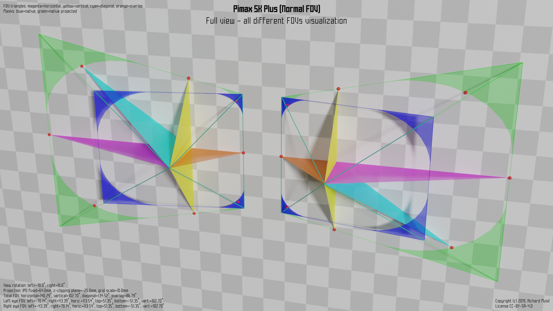
The HAM and the colored triangles for the different FOVs have been already described above. What is new is the green area, which is the projection of the blue shape into the parallel plane (with the face).
The blue area has the same meaning as in the previous example, i.e. it represents the (rectangular) shape cut of the viewing frustum, or, if you want, the space into which the renderer fits the image. It is just canted 10° outwards.
The general formulas to calculate all the different FOVs are still the same as in the Vive’s case, just the values are different, and one needs to take the panel rotation into account, when dealing with raw numbers.
One thing to point out though. The green area’s (trapezoid) shape means that the vertical viewing range, observed in the plane parallel to the face, is not constant when moving from the nose to the outer edge. Because of that the vertical FOV is defined as a vertical range observed when the both views are parallel (i.e. the eyes are looking in the same direction, straight ahead). The corresponding FOV points reflect that in the illustration.
All the figures would be fine if all the headsets were honest about their geometry and did not cheat. They mostly do not (and for their defense, if they do, it is not because they want to), but some do, and some do even more. Welcome to the world of parallel projection.
Parallel projection
Both the blue and the green “holes”, i.e. what is not actually colored inside the colored shapes in the previous picture, cover the exactly same field of view. The only difference is that the shape of the blue one has the rectangular form (good for the rendering engines), while the green one is a trapezoid, not particularly appealing to the rendering. In fact, the only way to render into such a shape is to render into a superior rectangle and mask all the surface, which is not used.
The implication is that if someone would want to use (for some technical reason) the green shape to cover the same FOV as the blue shape, he will inevitably waste some resources. Even if the pixels are masked, the geometry still needs to be processed.
In order to not lose precision in the transformation from the green shape to the blue shape, some overhead (supersampling) is also needed.
Since it does not seem to look like a good idea, the question is, why would anyone want to do that? The answer is simple. They have no choice. Unfortunately, there is still a lot of VR applications, which were developed with an (unsupported) assumption that the stereo rendering always happened into parallel views and went a long way to optimize their code around this assumption.
Even Nvidia’s first hardware support for the stereo view rendering only worked on parallel views. Before Pimax, the world was only parallel. Now, the demand for the non-parallel rendering already reached the developers and the hardware designers, but there is still a lot of work to do. And some applications are simply stuck with their implementation for ever.
So to accommodate all those unfortunate cases, the parallel projection mode was introduced. In this mode the headset behaves as if it has the parallel view geometry and pretends to the VR subsystem that all is right and shiny, while doing some nasty tricks afterwards, to put those parallel images onto its non-parallel screens.
The following picture illustrates how things get messy in this mode. (Courtesy of Pimax 5k+, Normal FOV, PP mode off (blue and green) and PP mode on (red)):
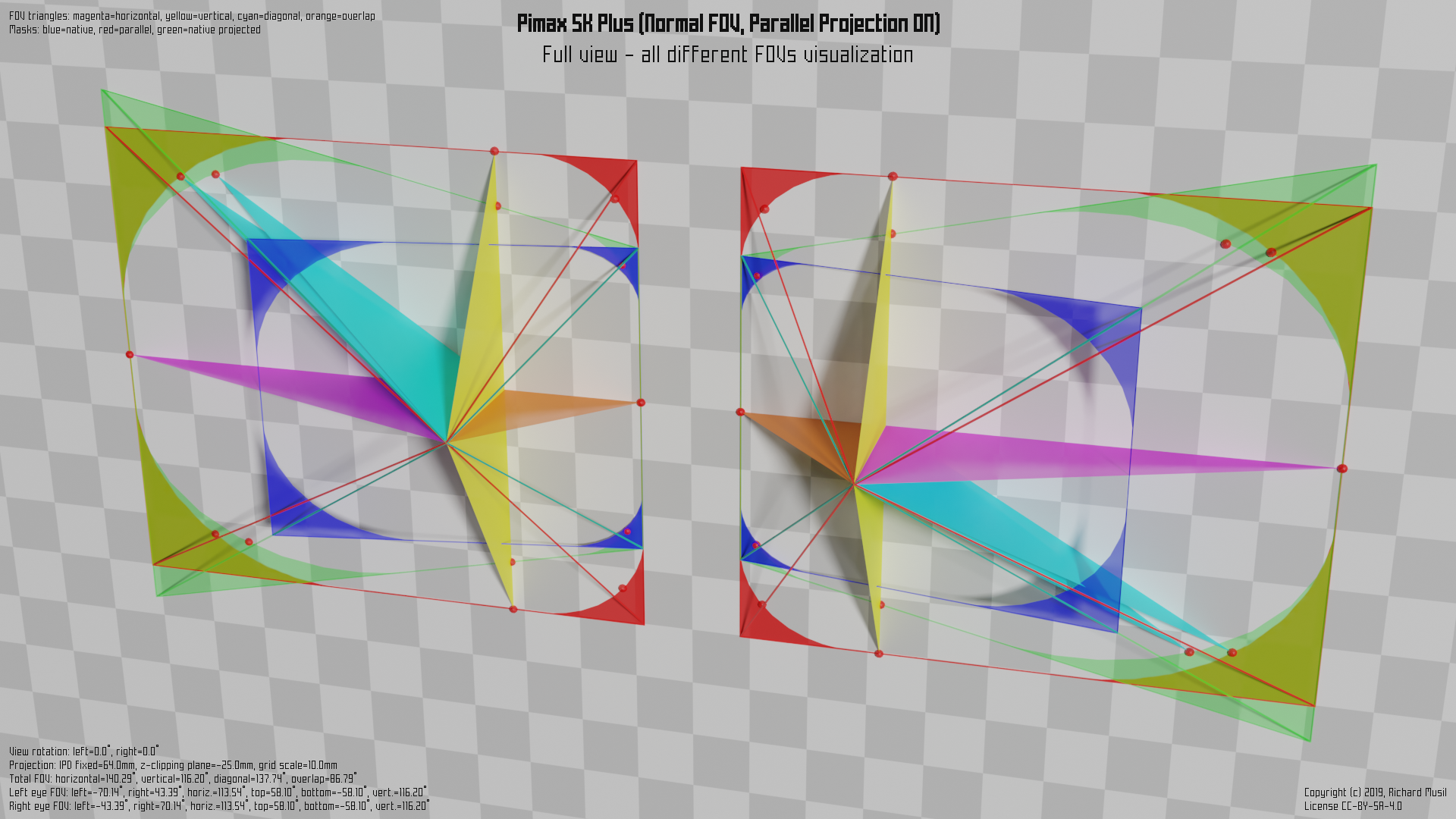
First you may notice that in order to keep the rendering overhead on the manageable level, the red rectangle (which is the shape of the “pretended” parallel stereo view the headset supports) does not completely cover the green one. The outer green corner tips are cut off. Fortunately this is not a problem as they are already in the masked area (the green surface is the projection of the blue masked area).
The problem however appears at the inner parts of the views, where the red shape not only fairly surpasses the green outline, but Pimax did not even bother to define correctly the HAM for the parallel projection (red) rectangle, so everything rendered into the “red hole” outside of the green outline is wasted.
In fact, to further optimize the performance requirements, they could make the red rectangle vertically smaller to match the non-masked green area height and then mask the rest by the HAM.
The other unpleasant consequence of this mode is that it messes up the calculation of the vertical FOV, because the one reported by the headset is a false one. If you check the position of corresponding FOV points for both the green and the red vertical FOVs, you may notice that they do not align (as well as those for the diagonal).
And the last, but not least, effect is that it introduces a different perceivable pixel density at the inner and the outer border of the single eye view.
This also means:
If you use
hmdqto calculate the vertical FOV of the headset, do not run it when the headset is in the parallel mode.
If you do, you can get incorrect (bigger) values.
Valve Index
Valve Index is another headset which uses canted displays and the parallel projection.
While Pimax definitely has its issues with the parallel mode, they, at least, give a clear indication that the parallel mode is on and offer some user interface to control this feature.
Valve, on the other hand, decided that the best thing will be to turn this on by default on everyone and do not indicate anything. So, if you are using the Index and your are not sure, whether you have this feature enabled, you most likely have.
If you want to make sure, you can check it by running hmdq and see View
geometry section in its output. If it says:
View geometry:
left panel rotation: 0.0 deg
right panel rotation: 0.0 deg
then you are using the headset in the parallel projection mode.
Rendered FOV versus the visible one
Finally, all the calculations described above, in particular the calculation of
the FOV points and subsequent rendered FOVs can be performed by the command
line tool hmdq which queries the headset
over OpenVR API (the same way as any other VR application does), collects all
the necessary data advertised by the headset, and does the math.
The important aspect of this calculation is that it gives reproducible and measurable results, independent of all the variable aspects, which otherwise also influence what the user actually can see in the headset. Among those variable aspects are: the face shape, the eye depth, the distance from the eyes (facepad thickness), the field of view of the lenses, interpupillary distance (IPD), etc.
The FOVs described in this article are technical conditions at which the headset operates and at which the application renders the scenes. The user cannot see “more”, because “more” is not rendered by the application. The user can however see less, depending on how all the individual aspects named above impact the whole optical path from the panels to the eyes.